Drawing an hexagonal grid with a shader
Tilemap VS Shader
I have a worldmap made of hexagonal tiles, and I have been using a “tilemap” object from godot to draw it. But this tilemap has quite a few limitations:
- it can get very laggy when the grid is large, which means I have to split it in smaller patches.
- it is slow to load. Which means either some lag when loading a new patch, or extra complications to handle async loading.
- and it is not simple to get smooth transitions between tiles.
So far we handled the transitions by having tile images larger than the actual hexagons, and a semi-transparent border. This method however does not work so well when the transition between two area should be sharp.
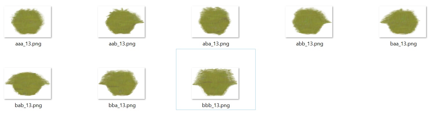 Examples of tiles from the plain biome. Each tile fully covers its hexa, plus part of the neighboors to hide the transitions
Painting the whole worldmap with a single shader
So … what if I could ditch the tilemap and draw the whole map with one single shader? It is basically what proposes this tutorial Instead of a set of tiles, it just requires a seamless texture for each biome and paints the whole world in one single shader pass.
The overall idea is this:
- define a seamless texture for each tile type (ie each biome)
- pass all these textures to a shader
- also pass the tiles data to the shader
- at each pixel, the shader retrieves the current tile and its neigbors, query the color for current tile and for neighbooring tiles from the textures, and blend these colors with a bit of magic.
So … I just have to implement this tutorial, right?
Except there is a complication of course. The tutorial above works with a square (or rectangular) grid, while I have an hexagonal grid.
Adapting the shader to hexagonal tiles
The overall idea is the same:
- We pass a texture for each biome to the shader (with a textureArray instead of the giant texture used in the linked tutorial, this seems simpler and made exactly for such use cases.)
- we also encode the id (in the array) of the texture used by each tile in texture which is passed to the shader.
- and we will discuss the blending later.
To do that, we will need some primitives to retrieve to which hexagonal tile belongs a pixel. In the square case, this is made with a simple ‘Round’. The hexagonal case is a bit trickier. But thanksfully, there are very good ressources on this topic on the net, and in particular there is the hexagonal Bible: redblobgames . If you want to work with hexagons and did not know this site, I would really advise to bookmark it.
The simple version of the shader, with no blending between tiles, looks like this:
void fragment()
{
	// pixel position scaled to hexagon size
	vec2 xy = UV * WorldPixelSize / CellSize ;

	// Retrieve hexa containing current pixel
	ivec2 currentHexa = GetTile(xy);

	int tileId = getTileId(currentHexa);
    // blend these colors according to weighting
	COLOR = getColorForCurrentPixel( UV * WorldPixelSize , tileId );
}
You can find the full implementation here
Obviously, when using this shader, the hexagonal tiles are clearly visible:
Blending the tiles
Well, this is where the fun begins. The square-case tutorial above was using a blending texture to weight the color from current tile and its neighbors, but I did not manage to transpose his method directly to the hexagonal case.
So, how should we blend? Actually, the first question is: what should we blend? An hexagon has 6 neighboors, should we blend together the 7 neigbooring textures (6 neighboors + current)? It might be an option, but seems quite overkill.
Finding neigbooring tiles
Instead, let us use some property of the hexagonal geometry: Each point x of the plane is inside the triangle formed by the centers of the 3 hexagons nearest from x, and these triangles don’t overlap.
![hexa with 6 neigbors, and triangle made by 3 closest hexas] (/assets/images/hexashader/hexas.jpg) The triangle made by the 3 nearest centers (red) contains current point (red spot)
This mean we can only blend together the 3 textures from the 3 nearest neigboors from a point. To find these neigbors in shader code, I just run a for loop on the 6 possible neigboors:
	ivec2 hexa1 = GetTileInAxialCoo(xy);
   // Find the two next nearest neigbooring hexagons.
   // Current point should be in the triangle defined by the centers of these two hexagons and the center of current hexagon.
   float dist2 = 100.;
   float dist3 = 100.;
   ivec2 hexa2;
   ivec2 hexa3;
    // iterating on each neigboor of current hexagon ...
	for (int i = 0; i < 6; i++)
	{
		ivec2 currentHexa = hexa1 + dirs[i];
		vec2 tileCenter = TileAxialCooCenter(currentHexa);
		float currentDistance = d2(xy , tileCenter);
	    if( currentDistance < dist2 )
		{
			hexa3 = hexa2;
			hexa2 = currentHexa;
			dist3 = dist2;
			dist2 = currentDistance;
		}
		else if(currentDistance  <  dist3 )
		{
			hexa3 = currentHexa;
			dist3 = currentDistance;
		}
	}
Barycentric coordinates
We have now retrieved the 3 hexagons nearest from current point. For each of these 3 hexagons, we can query the texture id from the grid data; and we can retrieve the color of this texture at the current point. To blend these 3 colors, we should now assign a weight to each of the hexagons.
A natural way to assign these weights is to compute the barycentric coordinates of current point, in the triangle made from the three hexa centers. Indeed these barycenyric coordinate can be directly interpreted as of “weight” of each center on current point, and they have all the required properties:
- they are continous functions of the current pixel position
- on an edge of the triangle, the weight of the opposite vertices is 0 (So when we cross this edge, we enter in another triangle where this vertices is not part of the mix, its weight is thus implicitly 0 there. By continuity it must be 0 on the edge.)
- the maximum weight is always the weight of current hexagon. (This means we might use a softmax to smoothly interpolate between belding / no blending)
Computing barycentric coefficients in the shader is quite straightforward:
vec3 BarycentricCoefs( vec2 center1, vec2 center2, vec2 center3, vec2 xy)
{
    vec2 px = xy - center1;
    vec2 py = xy - center2;
    vec2 pz = xy - center3;
    float alpha = det2(py, pz);
    float beta = det2(pz, px);
    float gamma = det2(px, py);
    float sum = alpha + beta + gamma;
    return vec3 ( alpha / sum , beta / sum, gamma / sum );
}
Noisy barycentric coordinates for less regular transitions
Now, to avoid having always the same transition on each corner, we can inject some noise to the barycentric coordinates. To make sure this noise is continuous, we use a noise texture. And to noise differently the 3 coordinates, I am using 3 chanels of the same texture. Here is the noisy texture I am using:
 64x64 seamless noise texture made with gimp
float GetNoiseChanelAt( vec4 noiseColor, ivec2 hexa_axialcoo  )
{
    int hexaColor = (hexa_axialcoo.x - hexa_axialcoo.y) % 3;
    // switching chanel depending on "hexaColor"
    return (hexaColor == 0)? noiseColor.g :
         ((hexaColor == 1)? noiseColor.b : noiseColor.a );
}

    vec4 noisecolor = texture(noiseTexture, xy * barynoisescale );

	float noise1 =  GetNoiseChanelAt(noisecolor , hexa1 )* barynoiselevel + 1.;
	float noise2 =  GetNoiseChanelAt(noisecolor , hexa2 )* barynoiselevel + 1.;
	float noise3 =  GetNoiseChanelAt(noisecolor , hexa3 )* barynoiselevel + 1.;

	barycentric *= vec3( noise1 , noise2, noise3 );
There are a few tricks in the code above to ensure that the weights are continuous functions of the pixel’s position:
- the choice of the chanel at each hexa must not depend on point xy. For example we cannot just assign the first chanel to hexa1 … Instead, I use a 3-coloring of the hexagonal grid to assign a chanel to each hexa.
- the noise is applied with a multiplication, not an addition: Remember, on an edge the weight of the opposite vertice must be 0, and additive noise would not preserve this property.
Results
The final shader contains a few other improvements I don’t have time to describe today. But you can find my shader code here: shader code And contact me if you have some questions!
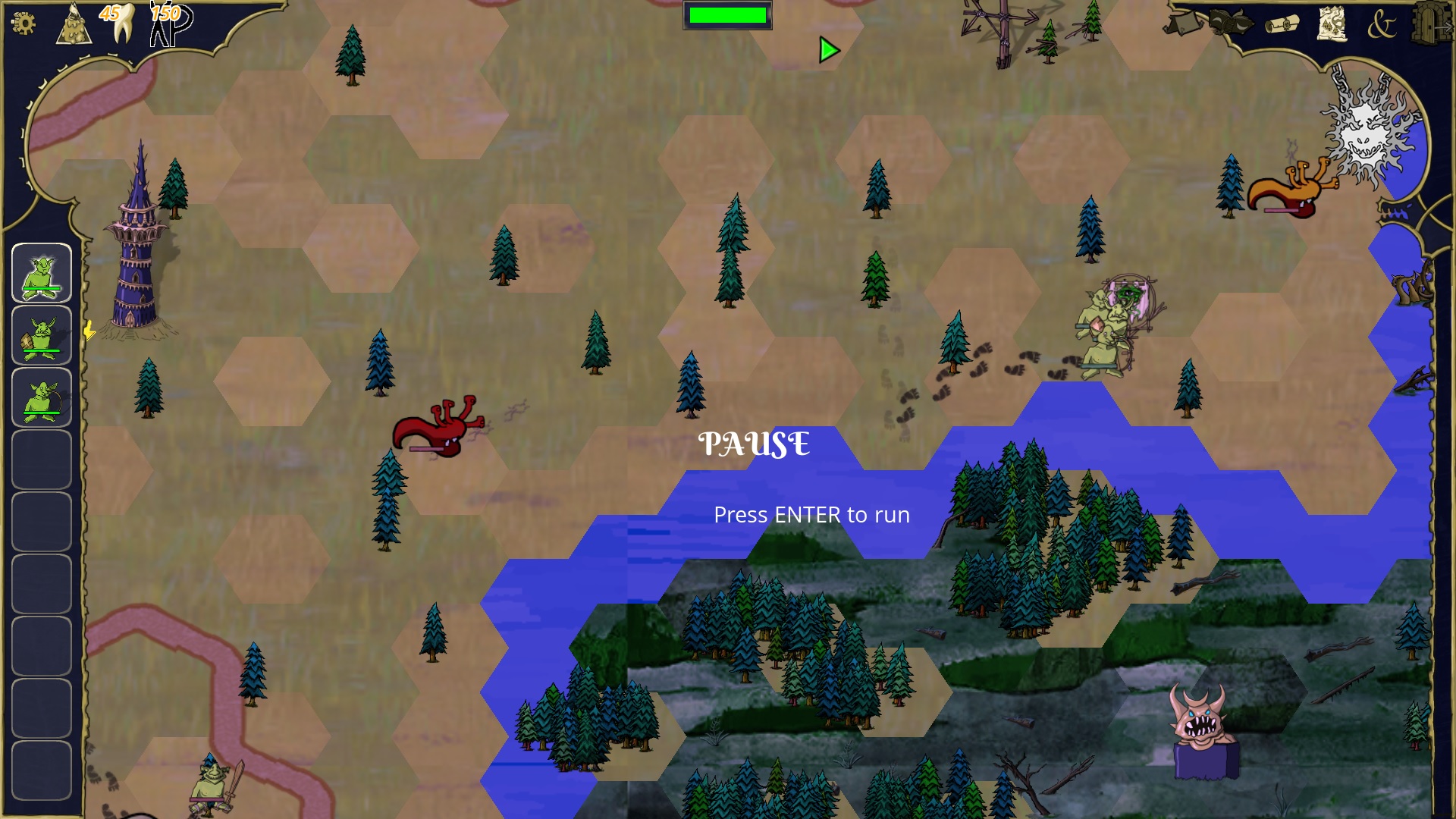
And finally, here is a screenshot of how the world is rendered with this shader:
 There are a few visual artifacts, mostly because my textures are not seamless. Indeed I just pluged whatever textures were available; now I need to whip my brother and maybe he will make better textures!
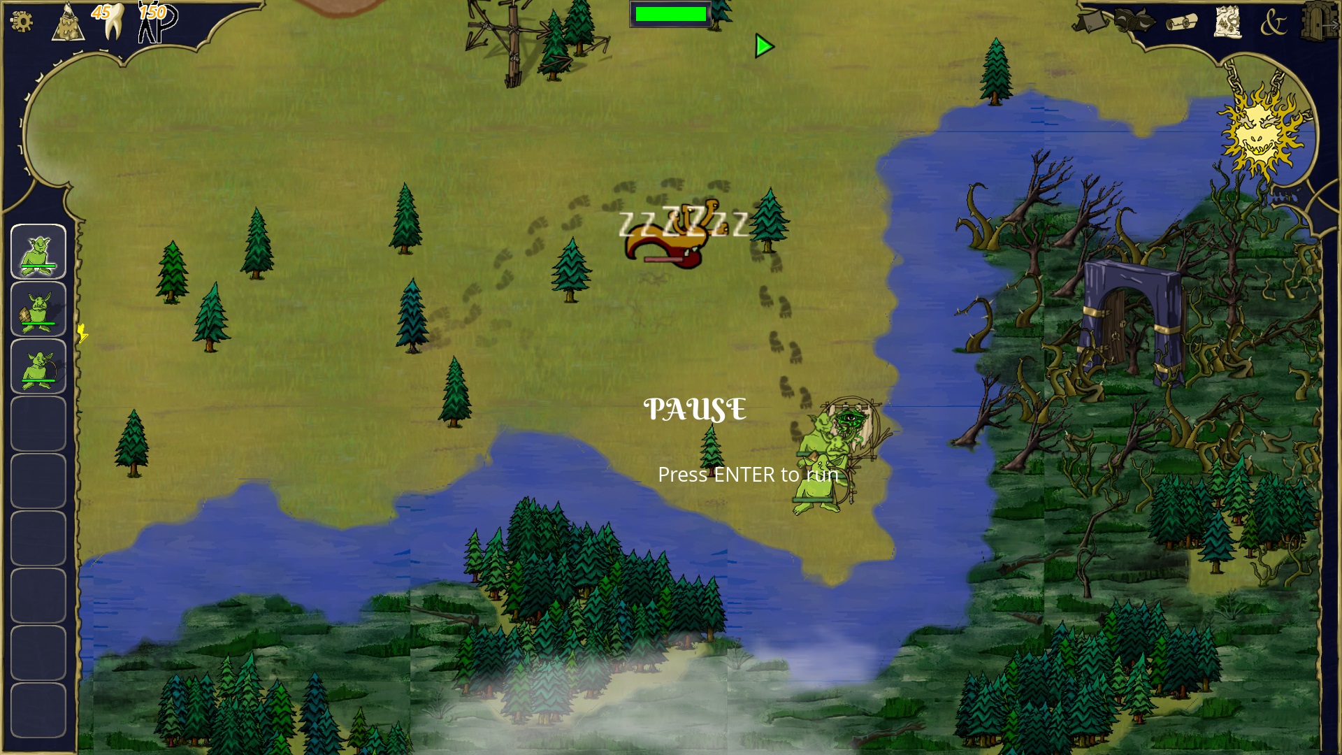
As a comparison, the image below was using a good old tilemap, with tiles partially overlapping:
 Note in particular the border of the river, where the hexagons are quite visible.